
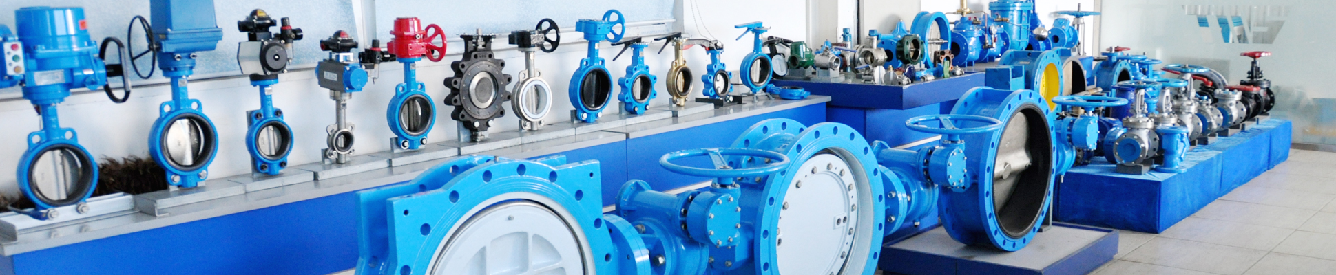
What Is an Electric Actuator?
An electric actuator is a self-contained electromechanical assembly that converts electrical energy into controlled motion—rotary or linear—to operate a valve. It comprises an electric motor, a gear reduction train, a control module, and an output interface that couples to the valve stem. Unlike a pneumatic actuator, which depends on a continuous compressed-air supply, an electric actuator holds the valve in position without drawing power once the commanded position is reached. This characteristic makes electric actuation the preferred choice where compressed air is unavailable, where precise intermediate positioning is required, or where the valve must remain in its last position on loss of command signal.
For a parallel treatment of air-driven systems—including double-acting versus spring-return logic and pressure-dependent torque—the pneumatic actuator selection guide provides the corresponding framework.
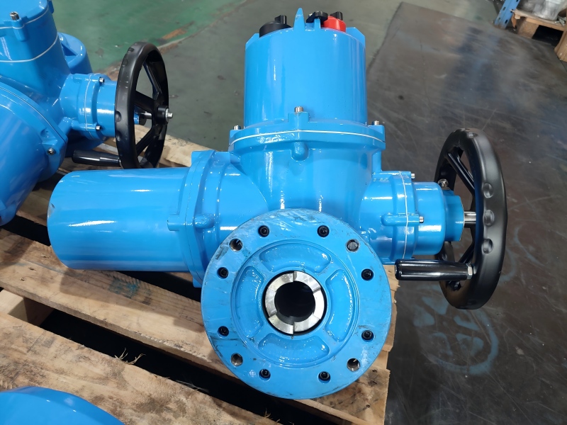
How Electric Actuators Work
The energy conversion path follows a fixed sequence: motor → gear train → output shaft. A reversible induction or DC motor rotates at high speed and low torque. The gear train—typically a combination of spur gears and a worm or planetary reduction stage—converts this into low-speed, high-torque rotation. The output shaft is coupled to the valve stem through a standardized mounting interface. For quarter-turn service, the shaft rotates through 90°; for multi-turn service, it completes multiple revolutions to drive a threaded stem nut.
The practical engineering consequence is that output torque is not a fixed constant. It depends on motor starting characteristics, gear efficiency, supply voltage, ambient temperature, and duty cycle. A motor rated at a nominal torque under continuous duty may deliver a higher breakaway torque for a short duration, but thermal protection limits sustained overload. This is why selection must be anchored to the valve’s breakaway demand, not its running torque.
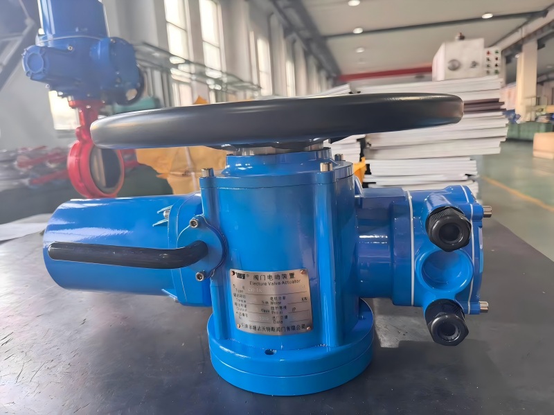
Main Electric Actuator Types
|
Type |
Output Motion |
Valve Match |
TWS Range |
|
Quarter-turn |
90° rotation |
Ball valves, cast iron butterfly valve |
30–2,000 N·m (standard); 50–1,000 N·m (explosion-proof) |
|
Multi-turn |
Multiple 360° revolutions |
Gate valves, globe valves |
HYZ series (on/off and modulating) |
|
Linear |
Axial thrust |
Globe valves, special linear-stroke applications |
Available on request |
The quarter-turn and multi-turn families are the primary selection paths. The choice is dictated by the valve stem’s required motion—not by actuator preference or catalog availability.
Quarter-Turn Electric Actuator
A quarter-turn electric actuator rotates the valve stem through 90° between the fully open and fully closed positions. It is the standard actuator for ball valves and butterfly valves. TWSs quarter-turn range includes on/off, 4–20 mA modulating, and intelligent modulating variants, with a torque range of 30–2,000 N·m and stroke times of 5–60 seconds depending on the model. Enclosures are die-cast aluminum with polyester coating, rated IP67 electric actuator as standard with IP68 available on request. Mounting follows ISO 5211, the international standard for part-turn actuator attachments, which specifies flange dimensions and drive interface geometry to ensure interchangeability between actuator and valve. The quarter-turn electric actuator family organizes these configurations by control type and torque class.
A mini plastic variant is available for small valves and space-constrained installations. These units deliver up to 30 N·m with a 5–15 second stroke time, a reinforced engineering plastic housing rated IP67, and AC 220 V or DC 12/24 V supply options. They are suited to laboratory, chemical dosing, and light-duty HVAC applications where a conventional industrial actuator would be oversized.
Multi-Turn Electric Actuator
A multi-turn electric actuator produces multiple revolutions at the output shaft, driving valves that require a threaded stem to travel linearly through a yoke—most commonly gate valves and globe valves. The critical sizing output for multi-turn service is stem thrust, not pure rotational torque. The actuator’s torque is converted to thrust through the stem thread; the thread’s lead and efficiency determine how much linear force is produced per unit of torque. The HYZ series is available in on/off and modulating configurations, integrating fieldbus communication and absolute encoding for position feedback. The number of output revolutions must match the valve’s stem travel requirement, and the breakaway thrust—not running thrust—is the sizing case, particularly after prolonged closure under differential pressure. The multi-turn electric actuator range provides the starting point for gate and globe valve configurations.
On/Off vs Modulating Control
The control intent determines the actuator’s internal electronics and its interface with the plant control system. It is a functional decision, not an accessory choice.
|
Control Type |
Command Signal |
Behavior |
Typical Application |
|
On/Off |
Discrete (dry contact or pulse) |
Drives to fully open or fully closed; no intermediate positioning |
Isolation valves, batch sequencing, emergency shutoff |
|
Modulating |
4–20 mA, 0–10 V, or fieldbus |
Positions the valve proportionally to the command signal |
Flow control, pressure regulation, temperature loops |
TWS’s modulating quarter-turn actuators accept 4–20 mA input, with intelligent models supporting digital communication and 0.5% repeatability for precise positioning. On/off units use floating switch control. The distinction matters beyond signal type: modulating service imposes more frequent motor starts and reverses, increasing thermal load on the motor and gear train. An actuator sized for on/off duty at a given torque may need to be upsized for modulating duty at the same torque to account for starting frequency and positioning accuracy requirements.
How to Size an Electric Actuator
Sizing is a sequential engineering process, not a catalog lookup:
- Establish the valve’s required torque or thrust. Obtain break-to-open (BTO), running, and seating values from the valve manufacturer. For multi-turn valves, obtain the required stem thrust and stem thread specification.
- Apply a safety factor. The sizing margin accounts for uncertainty in valve torque data and operating conditions. A minimum factor of 1.3 (30% margin) is a widely used baseline for general service. For safety-critical or poorly characterized service, a factor of 2.0 may be appropriate.
- Check output at the actual supply voltage and duty cycle. Catalog torque is typically stated at a specific voltage. If the site voltage differs, available torque changes. For DC supply, rated current is substantially higher than for AC at the same output class.
- Verify travel and coupling compatibility. Quarter-turn actuators must produce 90° ± adjustment; multi-turn actuators must produce the required number of revolutions. The output drive (square, star, or keyed) must match the valve stem, and the mounting flange must conform to ISO 5211 for mechanical interchangeability.
- Confirm control, protection, and environment. Match the command signal to the control system, the IP rating to the installation environment, and the explosion-proof classification to the area classification.
Valve Torque Requirements
Valve torque is not a single number. It varies across the stroke and depends on valve type, seat material, pressure differential, and fluid condition.
|
Torque Component |
When It Occurs |
Sizing Significance |
|
Break-to-open (BTO) |
Start of opening from seated position |
Usually the highest demand for ball valves; must overcome seat interference and differential pressure |
|
Running torque |
Mid-travel |
Lower than BTO for most quarter-turn valves; relevant for continuous modulating duty and thermal sizing |
|
Seating / end torque |
At the closed position |
Can be high for butterfly valves with elastomer seats; the actuator must complete the stroke without stalling |
The actuator is sized against the highest of these values. Sizing against running torque is a common error that produces an actuator that performs correctly on the bench but stalls in the field when the valve has been closed under pressure.
Safety Factor: How Much Margin Is Enough?
The safety factor is a deliberate engineering margin, not a commercial allowance. A 1.3 factor (30% above the calculated valve torque) is a practical minimum for general on/off and modulating service with reliable torque data. For safety-critical applications—emergency shutdown, highly viscous or solidifying media, or service where torque data is uncertain—a factor of 2.0 is frequently specified. The consequence of an insufficient margin is not immediate failure; it is a valve that operates reliably under favorable conditions and then fails to open when the medium is cold, viscous, or at high differential pressure—precisely when operation matters most.
Operating Time
Operating time is a function of motor speed, gear ratio, and stroke length. TWS’s quarter-turn range spans 5–60 seconds for 90° travel depending on model and torque class; mini units complete 90° in 5–15 seconds. Operating time becomes a binding constraint in two scenarios: emergency isolation, where the valve must close within a defined safety time, and fast-cycling modulating service, where the actuator must track a command without excessive lag. A faster actuator generally requires a larger motor and a different gear ratio, affecting power consumption and heat generation.
|
Supply Voltage |
Typical Application |
Engineering Note |
|
DC 12/24 V |
Remote sites, control-panel power, solar/battery systems |
Higher current draw per output class than AC; power supply must be sized for inrush |
|
AC 110 V |
Single-phase systems, legacy installations |
Common in North American and some export markets |
|
AC 220 V |
Single-phase industrial and commercial power |
Widely used in TWS’s standard quarter-turn and mini ranges |
|
AC 380 V |
Three-phase industrial power |
Required for higher torque models and large multi-turn applications |
Specifying the wrong voltage is not a minor configuration error. It can damage the motor winding and control electronics and voids the unit’s protection ratings. The site supply must be confirmed before order placement.
Control Signals: Analog and Fieldbus
The command signal determines how the actuator receives position instructions and reports status. 4–20 mA remains the dominant analog standard in process control because its live zero (4 mA) distinguishes a valid minimum command from a broken wire, and it is more tolerant of electrical noise over long cable runs than voltage-based signals. 0–10 V is common in building automation and shorter-cable applications. Fieldbus protocols—including Modbus and Profibus on intelligent models—provide digital position feedback, diagnostics, and multi-drop wiring. The signal must match the plant’s DCS or PLC interface; an actuator with a 4–20 mA input cannot be driven by a discrete output module without conversion.
IP Protection: Matching the Enclosure to the Environment
TWS electric actuators are rated IP67 as standard across quarter-turn, multi-turn, mini, and explosion-proof ranges. IP67 denotes dust-tight construction and protection against temporary immersion (up to 1 m for 30 minutes). This rating is sufficient for outdoor installation, washdown in food and beverage areas where directed high-pressure jets are not used, and humid or dusty industrial environments. IP68 is available on request for applications requiring prolonged submersion, but it is not the default and should be specified explicitly when conditions demand it. An inadequate IP rating does not cause immediate failure; it produces moisture ingress that degrades insulation, corrodes terminals, and creates intermittent faults that are difficult to diagnose.
Manual Override: Emergency Operation
TWS electric actuators are equipped with a manual override—lever or handwheel—for operation during power failure or emergency conditions. The override allows valve positioning without electrical power, which is essential for commissioning, maintenance, and recovery from supply interruption. A critical operational rule applies: do not engage the override while the motor is energized. Doing so can damage the gear train or the override mechanism. The override type and accessibility should be confirmed at the selection stage, particularly for actuators installed in remote or unmanned locations.
Electric Actuator + Ball Valve
Ball valves present a torque profile dominated by break-to-open torque, which can be two to three times the running torque depending on seat material, pressure class, and whether the valve has remained in one position for an extended period. A quarter-turn electric actuator is the correct family match. The sizing sequence is: obtain the ball valve’s BTO torque at the maximum differential pressure, apply the safety factor, and select the quarter-turn model whose rated torque at the site voltage exceeds the factored requirement. For isolation duty, an on/off unit is the economical choice; for flow or pressure control, a modulating unit with 4–20 mA input is required. The electric ball valve configuration path organizes valve-actuator combinations by body material, seat, and control type.
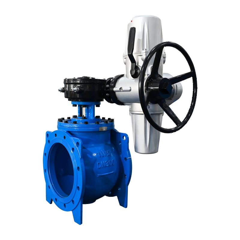
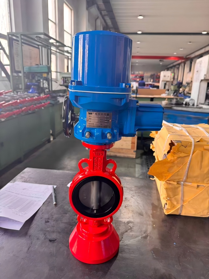
Electric Actuator + Wafer Butterfly Valve
Butterfly valves differ from ball valves in that torque is more sensitive to seat design and differential pressure. Elastomer-seated butterfly valves often exhibit a torque peak at or near the closed position, when the disc compresses the seat. Metal-seated or high-performance butterfly valves may have their highest torque at an intermediate angle during throttling. The actuator must be sized against the highest point on the specific valve’s torque curve, not a generic “butterfly valve” assumption. Quarter-turn actuators apply, with the same voltage, signal, and protection considerations as for ball valves. For large butterfly valves or high differential pressure service, the torque requirement may exceed the standard quarter-turn range, and a larger frame or a multi-turn actuator with a quarter-turn gearbox becomes the appropriate path. The electric butterfly valve selection path provides the corresponding configurations.
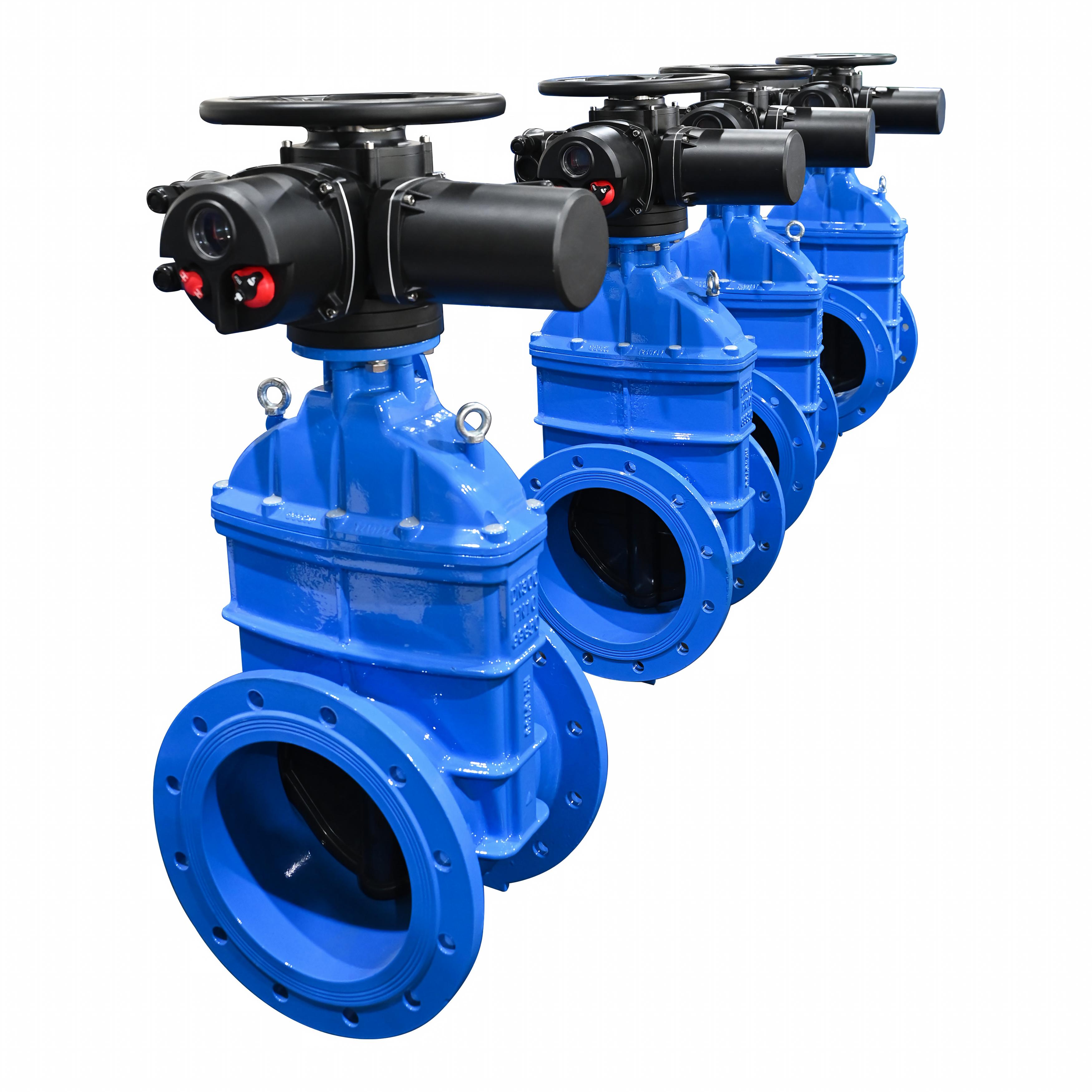
Electric Actuator + Gate Valve
Gate valves require linear stem travel, which means a multi-turn electric actuator driving the stem nut through the valve yoke. The sizing output is stem thrust, not rotational torque. The actuator’s output torque is converted to thrust through the stem thread; the thread’s lead and efficiency determine the thrust produced per unit of torque. The HYZ series is the family match, with on/off control for isolation and modulating control for throttling service. Breakaway thrust—not running thrust—is the sizing condition, particularly after prolonged closure under differential pressure. The electric gate valve selection path covers the multi-turn actuator and gearbox combinations for this valve type.
Electric Actuator Selection Matrix
|
If the application is… |
Actuator family |
Key sizing variable |
Critical specification |
|
Ball valve, on/off isolation, ≤ 2,000 N·m |
Quarter-turn on/off |
BTO torque × safety factor |
Supply voltage, IP67, manual override |
|
Ball valve, modulating flow control |
Quarter-turn modulating |
BTO torque × safety factor; duty cycle |
4–20 mA or fieldbus input |
|
Butterfly valve, general service |
Quarter-turn |
Peak torque across full stroke |
Seat material vs. torque curve |
|
Butterfly valve, high differential pressure |
Quarter-turn (large frame) |
Peak torque × higher safety factor |
Explosion-proof if area classified |
|
Gate valve, on/off isolation |
Multi-turn on/off |
Breakaway stem thrust |
Stem thread, travel revolutions |
|
Globe valve, modulating control |
Multi-turn modulating |
Thrust × safety factor; positioning accuracy |
Control signal, duty class |
|
Hazardous area (gas/dust) |
Explosion-proof quarter-turn or multi-turn |
Torque/thrust × safety factor |
ATEX/IECEx/NEC certification class |
|
Remote site, DC power available |
Quarter-turn DC |
Torque at DC voltage (higher current) |
Power supply capacity vs. rated current |
|
Compact installation, small valve |
Quarter-turn mini |
Running torque × safety factor |
Space envelope, IP rating |
Common Selection Mistakes
Sizing against running torque instead of breakaway torque. The actuator opens the valve on the bench, then stalls in the field when the valve has been closed under pressure. The breakaway condition is the sizing case.
Ignoring the voltage–torque–current relationship. A 24 VDC unit draws substantially more current than its 220 VAC equivalent for the same output class. If the DC supply cannot deliver the inrush current, the actuator will not produce rated torque.
Specifying IP68 without a submersion requirement. IP67 is sufficient for outdoor and washdown service. IP68 adds cost and is only necessary for continuous or prolonged immersion.
Treating explosion-proof as a housing upgrade. Certification covers the complete assembly, including cable entries and control components. Mixing certified and non-certified parts voids the certification.
Selecting a modulating actuator for on/off duty. The modulating electronics add cost and impose a different thermal duty profile. Conversely, an on/off actuator used for modulating service will experience excessive motor cycling and premature wear.
FAQ
1. Can a quarter-turn actuator operate a gate valve?
No. A gate valve requires multiple stem revolutions to move the gate through its full travel. A quarter-turn actuator produces only 90° of rotation and will not operate the valve. A multi-turn actuator is required.
2. What safety factor should I use for electric actuator sizing?
A minimum factor of 1.3 (30% above the calculated valve torque) is a practical baseline for general service with reliable torque data. For safety-critical, emergency shutdown, or poorly characterized service, a factor of 2.0 is commonly specified.
3. Is IP67 sufficient for outdoor installation?
Yes. IP67 denotes dust-tight construction and protection against temporary immersion, which covers outdoor exposure, rain, and washdown without directed high-pressure jets. IP68 is only necessary for continuous or prolonged submersion.
4. What happens if the supply voltage is lower than rated?
When the supply voltage is lower than the rated value, the available torque decreases..
5. Is manual override always available?
TWS electric actuators include a manual override (lever or handwheel) for power-off operation. The override must not be engaged while the motor is energized.
Post time: Nov-05-2026


